Tony Saxton

If we were playing straight poker, it would be a betting hand for sure. Unfortunately, we are talking aircraft maintenance here, so you can BET that “four of a kind” will not be a good thing. So here is the DEAL.
Over the last 12 to 14 months twin Cessna models has seen a great deal of aircraft ownership changes. This is great for our fleet, as new energetic owner’s breathe new life into underused and even long derelict aircraft. Lots of new avionics, repaints, engine/prop replacement and catching up on long needed maintenance is going on and this is wonderful! All this action makes our fleet much more viable and guarantees a reasonable number of highly capable models available for decades in the future.
As most of you have heard by now, this spring my shop has been loaded up with twin Cessna waiting on maintenance/inspections. Some of this backlog has been driven by this recent increase in prebuy evaluations and/or from owners with newly purchased aircraft trying to sort out those initial maintenance issues that a “new to you” aircraft bring. For us, it means seeing a lot of individual aircraft that we have never seen before, which brings me to the start of the following issue.
While working on these “new to us” models we suddenly encountered 4 aircraft in a row with brake issues. It would typically be reported as having no brakes on one side (oddly it was predominantly the right side) which would respond to adding fluid to the master cylinder or brake bleeding but would then rapidly reoccur. With four consecutive instances in a row consisting of two 414A’s, a 421C, and a 340A, this problem was now classified by us as a “trend”. We have seen the problem before, but only sporadically, and now it is becoming much more prevalent.
The problem lies inside the cabin under the floor. The brake system hydraulic lines only use rubber hose sections installed at the flexible connection points consisting of short loops from the rudder/brake pedals to connections at the first bulkhead under the floor, and from the landing gear wheel well side wall down the strut to the brake cylinders at the wheel. The rest of the system is made from sections of aluminum tubing with standard flared ends and the typical aircraft “blue” aluminum AN fittings. The tubing sections are fabricated from aluminum alloy of 5052 in the soft -O condition primarily is ¼” OD with a .035” wall thickness. This type tubing is excellent from a workability standpoint bending/forming well and will accept standard flaring without the need for special processes. Additionally, 5052 has the highest strength of non-heat treated aluminum, resists fatigue cracking caused by pressure cycles and vibration, and has good resistance to atmospheric corrosion. But “good resistance” should not be confused with impervious.
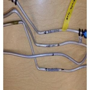
What we find is the aluminum lines under the floor will corrode to the point that they will develop pin holes (see picture) which allow the hydraulic fluid to escape. These holes are not normally big enough for a complete instantaneous loss of fluid but will lose a drop or two at each brake application until the reservoir is depleted and no braking is available. The lines are routed in and around various items such as cables, wiring, structure, and heating and cooling ducting. On the right side of the pressurized aircraft there is a large air ducting that the tubing passes over forcing it to lay on about a 3”-4” long area. The ducting black “CAT” type aeroduct has air passing through it that is frequently warmer than the surrounding area and will cause condensation to form on the cooler aluminum structure. Because the brake line lies against the ducting it will retain the moisture for a long time and also the ducting is made from silicon/fiberglass which as it ages will leach out mildly corrosive material.
Identification of corrosion is rather difficult. The areas under here are jam-packed with stuff and a large part of the floor sections, especially in the 400 series models, is not removable having only a few small inspection plates available to look through. This impedes visual discovery to a great extent. Even after the lines begin to leak its hard to find. The fluid loss is rather small and a good portion of it simply soaks into the aeroduct jacketing, thus not even dripping down to pool on the floor. Even if it is pooling as you will note all of these finds were in pressurized models, so the sealed cabins didn’t even allow for the fluid to drop out on the hanger floor as they sat.
Typically, this starts as just a mystery loss of brake hydraulic fluid that doesn’t show up anywhere but simply continues over and over again.
EVEN MORE PROBLEMS:
A continuation of this is to warn of other similarly affected systems. A good deal of other systems uses these types of aluminum lines for moving fluids and air throughout the aircraft also with many routed under the floor as well.
Original equipped “steam” gauges use them for gauge lined for the oil pressure, MAP, as well as for the Pitot/static system. Any of these can become corroded and leak. A number of years ago a 340A suddenly started to have unexplained left engine oil usage. Even with lots of detailed engine troubleshooting the oil consumption stayed uncharacteristically high. After a number of flights, it was found that the aluminum oil pressure line under the cabin floor had a pin hole and had allowed literally gallons of oil to seep out creating the oil consumption issue. The problem was easily fixed with a replacement line section, the oil mess clean up with places 3 or 4 inches deep took much, much longer.
Another even more concerning system is fuel lines that run under the floor. Fuel pressure gauges, fuel cross-feed lines and heater fuel feed lines are again all made from 5052-O aluminum. 340’s are frequent victims of corrosion line corrosion on the cross-feed fuel lines under the floor aft of the copilot’s seat. Once again it is and area where the line comes into contact with a cabin aeroduct resulting in several serious fuel leaks. Too, Cessna service Bulletins MEB04-1 and MEB95-9 warn of corroded heater fuel supply lines corroding and leaking.
OTHER AREAS:
Problems with aluminum lines are not just under the floor. Oxygen supply lines run throughout the upper cabin and multiple aircraft have experience corroded and leaking lines above the headliner. In an area not frequently inspected this issue should be suspected if very rapid oxygen depletion is detected during use. Any time there would be an event where the headliner was pulled down schedule and plan on very extensive inspection and possible replacement of the lines up there as it is normally the only time they are ever look at.
Behind cabin side walls run aluminum feed lines for pressurization control ducting, deice pressure for the tail boots, and static air from the aft ports to the forward cabin. Any of these has been seen to have corrosion issues.
The CALL:
These areas are hard to see with lots of deeply hidden areas, so it takes very detailed, often specifically called out location inspections to identify problems. I quick glance with maybe a flashlight just isn’t good enough.
Also, the culprit for these defects is corrosion and that isn’t always a function of operational hours, but simply time in service coupled by environment. Remember, even our very youngest represented model, the 1985 421C will soon be 40 years old and most models 50 and older.
Plan to take these areas seriously during inspection and build a detailed inspection plan so that when it’s time to “Show your Hand” you can beat “Four of a Kind”.


